
.jpg)
Calculation strategies to comply with the new CTE without adding unnecessary insulation. Since the publication of the new CTE, we have observed in various forums and webinars a certain concern with complying with the global K limit. To better understand this new metric, we explain its key parameters and how to optimize its calculation.
What is the global K? The key parameters
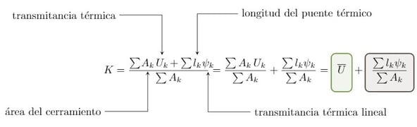
The global K can be understood as the weighted average of the thermal transmittance of each element of the thermal envelope according to its area. This envelope exchange area excludes party walls and any envelope in which it is considered that no heat exchange occurs. To the average thermal transmittance is added the presence of thermal bridges, whose contribution will be smaller the larger the envelope exchange area.
Increase the compactness of the building
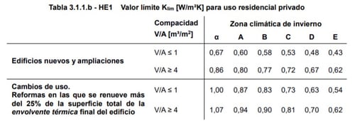
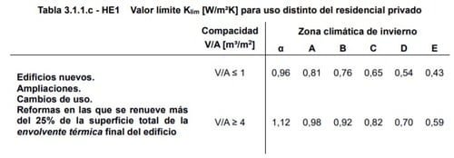
The HE1 of the new CTE limits the global coefficient of heat transmission (K) through the thermal envelope according to the winter climate zone and the compactness of our building. So, the less compact our building is and the more extreme the winter climate zone is, the more restrictive the new CTE is with the global K value.
Reduce the percentage of gaps
On the other hand, HE1 also limits the thermal transmittance of each element belonging to the thermal envelope, depending on its winter climate zone and the envelope boundary condition. In this way, the standard prevents the average thermal transmittance from complying with the global K limit by including envelopes with high thermal transmittance and being able to include them with others with low thermal transmittance.
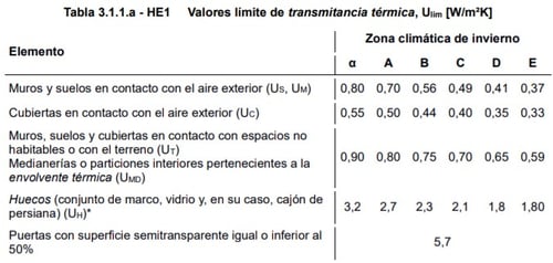
In the previous table, we observe that the transmittance limit of the openings is much higher than that of the opaque envelopes. One way to reduce the global K is to reduce the percentage of gaps in our project.
How is global K calculated?
We observe that reducing the thermal transmittance of an envelope is one of the key factors. The first thing to do is to calculate the thermal transmittance of an envelope.
The DB HE defines thermal transmittance as the heat flow, in steady state, for a unit area and temperature difference of the media located on each side of the element being considered. This temperature difference depends on the boundary condition of the element and can vary from envelope to envelope.
The DB HE Supporting Document indicates the procedure for calculating the characteristic parameters of the envelope which, translated into practice, adds a thermal resistance to the envelope depending on its boundary condition. Thus, all the envelopes come into contact with the outdoor air and justify the logic of making a weighted average of the thermal transmittances.
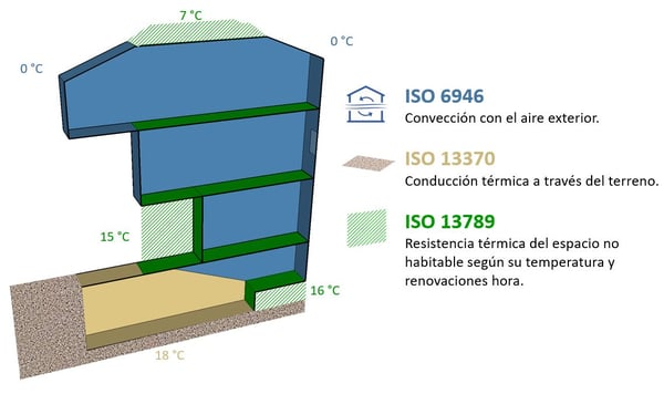
Once the thermal transmittance of each envelope has been calculated according to its external temperature, we must decide which envelopes to insulate in order to reduce its thermal transmittance. In this way, we can ensure compliance with the transmittance limit values and minimize the average thermal transmittance. However, for a correct calculation of the global K, we cannot forget the influence of thermal bridges.
How to avoid thermal bridges and reduce the global K?
To avoid thermal bridges, the building must be designed with continuity of insulation in the thermal envelope. Due to the unique characteristics of each building this design is not always possible, so it is necessary to study the thermal bridges individually, adding extra insulation where necessary to break the thermal bridge and reduce the thermal transmittance as much as possible.
For the calculation of thermal bridges, the DB HE has a Supporting Document with an Atlas that includes approximate values of thermal bridges for the most common construction details. These values are grouped by families of details and these, in groups ordered from best to worst performance. In the case that our construction details do not appear in the Atlas of thermal bridges, it is necessary to resort to specific two-dimensional modelling software, such as THERM.
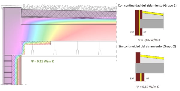
In the previous example we can see that, for a single construction detail calculated with THERM, an intermediate value is obtained to those proposed in the Supporting Document with and without continuity of insulation.
In order to optimize the calculation of the global K, we have developed a series of calculation tools that, starting from a model made with SG Save, take into account the thermal resistances of the different boundary conditions and calculate the thermal bridges automatically without having to consult the DB HE Supporting Documents.
This makes it easier for us to detect which elements of our envelope need insulation in order to comply with the new CTE, which is key to the development of nearly zero-energy buildings or nZEB.
